| |
http://wanclik.free.fr/fast_08.htm
http://wanclik.free.fr/fast_09.htm
http://wanclik.free.fr/fast_12.htm
http://wanclik.free.fr/fast_13.htm
http://wanclik.free.fr/fast_14.htm
http://wanclik.free.fr/fast_15.htm
http://wanclik.free.fr/fast_16.htm
http://wanclik.free.fr/fast_17.htm
http://wanclik.free.fr/fast_18.htm
http://wanclik.free.fr/fast_19.htm
http://www.univ-lemans.fr/enseignements/physique/02/electri/triphase.html
Mode triphasé
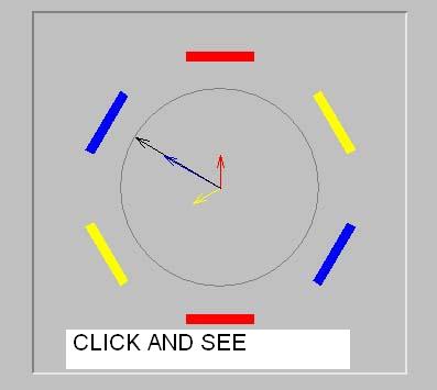
On considère trois paires de bobines plates identiques équidistantes de
l'axe du système et dont les axes font entre eux des angles de 120°. Elles
sont parcourues par les courants :
I1 = Io.cos(wt)
I2 = Io.cos(wt + 2p/3)
I3 = Io.cos(wt + 4p/3)
(Courant triphasé)
Dans la simulation, on trace l'évolution au cours du temps de l'induction
magnétique due à chaque bobine (trait de la couleur des bobines
correspondantes) ainsi que l'induction résultante (trait noir). Le module du
vecteur B reste constant mais ce vecteur tourne autour de O à la vitesse
constante wt.
C'est sur ce principe que sont basés les moteurs triphasés.

Dans chaque cas,
vous pouvez modifier la fréquence de rotation,
geler l'animation
et modifier le sens de la rotation du champ résultant.
Pour ce faire, on permute les courants dans les
bobines 1 et 2.

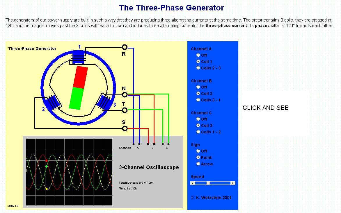
The Three-Phase Generator
The generators of our power supply are built in such a way that they are
producing three alternating currents at the same time. The stator contains 3
coils, they are stagged at 120° and the magnet moves past the 3 coins with
each full turn and induces three alternating currents, the three-phase
current. Its phases differ at 120° towards each other.
Generator design, frame size 710-1250
Quality throughout
All generators are tailor made within a standard, modular concept offering
great flexibility to ensure that correct generator characteristics are
selected for each installation.
- Compact and flexible design ensures a good match with the
plant's requirements.
- Rigid construction transfers dynamic and static stresses
directly to the foundation.
|
Rotor with salient poles and solid pole plates
- Ensures high thermal capacity and stability without the need for
special damping winding.
- Fast control and electric stability through adaptation of the
air gap, design of the pole shoes and dimensioning of the pole core.
- Solid pole shoes provide high damping without damper winding.
Good overload capability and low harmonics.
- Reliable operation and long service life ensured by large
cooling surfaces and effective flow of cooling air, which also
results in low, uniform rotor temperature. Class H insulation of the
coils gives extra thermal margins.
- Stiff rotor and minimized distance between bearings ensure low
vibrations since the operating speed is well below the first
critical speed.
- Over-speed tests are performed as standard. The complete rotor
is balanced at operating speed.
|
Stator design greatly influences stability and performance
- High-grade, low-loss electrical steel increases efficiency and
reduces operating costs.
- Stiff frame transmits all forces directly to the foundation.
- Well developed and proven methods for locking the coils into the
slots and bracing the coil ends ensure long term reliability.
- Insulation system that ensures reliability and long service
life. The windings are insulated with Mica based tape. When the
windings are in place, the complete stator is impregnated in a
vacuum pressure impregnation (VPI) process. The windings are of
insulation class F, resulting in good thermal margins.
- Voltage drop and short circuit current limitation are achieved
by designing the stator for optimized reactance values.
|
Bearings and bearing seats provide a reliable stator, rotor and
shaft assembly
- Bearing housing design permits easy access for inspection and
maintenance. The bearing housings are insulated from the frame to
eliminate circulating currents in the shaft. The shaft can be
earthed. Labyrinth seals are used to prevent oil leakage.
- Sleeve bearings are designed to be insensitive to misalignment
and to permit large axial play.
- Independent lubrication system gives high reliability. Oil rings
or oil reservoir ensure lubrication during emergency rundown.
Hydrostatic jacking oil systems are available for applications
operating at low speed.
|
Exciter mounted external to the non-drive end bearing
- Simple but highly developed design having few components and
well adapted protection functions offers high reliability and easy
access for maintenance.
- Compact, brushless exciter unit is mounted on the rotor shaft
outboard the bearing together with a PMG (permanently magnetized
auxiliary generator). No independent support or alignment is
required.
- Improved system performance due to high field forcing
possibilities. This is important when faults in the supply network
arise and when increasing production of reactive power.
|
Efficient cooling
- Very good cooling is obtained thanks to the the symmetrical
cooling achieved with the shaft mounted fans, in combination with
the design of the rotor and stator.
- The wide line of cooling forms allows an optimum for the
operating and environmental conditions of each application.
|
|
3. Features and Operating Performance
http://aemdessau.de/katalog/syn/english/s03.html
3.1. Voltage and Frequency
The generators are manufactured for all rated voltages recommended in
the IEC Directives and DIN EN 60034-1 up to 6900 V at either 50 or 60
Hz. For 230 V generators please note power according to Section 3.2.
Generators for special voltages and other frequencies can be supplied on
request.
3.2. Continuous Power Output
The rated power outputs listed in the type summaries apply for:
- Continuous
operation S1 at 50 Hz rated frequency
- Power factor
cosφ 0.8 (over-excited)
- Cooling air
temperature 40°C
- Installation
height up to 1000 m above sea level
- practically
sine form load current
- symmetrical
phase winding load
With different power factor, cooling air temperature and installation
height values the permissible continuous power output can be taken from
Tables 3 & 4. If the cooling air temperature reduces with installation
height by approx. 1°C per 100 m then the rated power output can be
retained. With any other deviations please consult the manufacturer.
This applies particularly for the static inverter load (see Section
3.12). During operation at 60 Hz the power output increases by approx.
20 % compared to the 50 Hz power output. Generators with 230 V can be
supplied up to a power output of 630 kVA.
|
Table 3 - Changing of Rated Power Output in Dependence of Cooling
Air Temperature and Installation Heigh |
| RT/°C |
30 |
35 |
40 |
45 |
50 |
55 |
60 |
| H/m above
sea level |
PS/PN |
| up to 1000 |
1.06 |
1.03 |
1.00 |
0.96 |
0.92 |
0.88 |
0.84 |
| up to 2000 |
1.02 |
0.99 |
0.96 |
0.92 |
0.88 |
0.84 |
0.80 |
| up to 3000 |
0.97 |
0.94 |
0.91 |
0.87 |
0.83 |
0.79 |
0.75 |
| up to 4000 |
0.91 |
0.88 |
0.85 |
0.81 |
0.77 |
0.73 |
0.69 |
|
Table 4 - Changing of Rated Power in Dependence of Power Factor |
| cosφ |
0.7 |
0.6 |
0.5 |
0.4 |
0 |
| PS/PN |
0.94 |
0.89 |
0.85 |
0.82 |
0.80 |
3.3. Overload Capacity
At rated voltage the generators can be loaded with the 1.5 x rated
current up to a period of 2 min at cosφ = 0.5 and once within 6 hours
with 1.1 x rated current for 1 hour. Short term current overloads that
occur when e. g. large asynchronous motors are connected are
permissible. The excitation device is designed in such a way that the
rated voltage is retained with a tolerance of approx. - 5 %.
3.4. Marine Classification
All generators for marine applications (Diesel generators, PTO
generators, static frequency inverter for mains separation etc.) are
supplied in accordance with the regulations of the following
classification societies as standard. If supply in accordance with other
classification societies is required please consult the manufacturer.
|
Table 5 - Reduction in Power Output for on Board Ship Applications |
|
Organisation |
Coolant
temperature °C |
Reduction
Factor to PN |
| ABS |
American
Bureau of Shipping |
50 |
0.92 |
| BV |
Bureau
Veritas |
45 |
0.96 |
| CCS |
China
Classification Society |
45 |
0.96 |
| DNV |
Det Norske
Veritas |
45 |
0.96 |
| GL |
Germanischer Lloyd |
45 |
0.96 |
| LRS |
Lloyds
Register of Shipping |
45 |
0.96 |
| MRS |
Maritime
Register of Shipping |
45 |
0.96 |
| RINa |
Registro
Italiano Navale |
45 |
0.92 |
Compared to the dry land versions according to Table 3 up to Table 4
the reductions in power listed in Table 5 result from the increased
cooling air temperature and the permissible winding temperatures laid
down by the societies. For marginal applications please consult the
manufacturer.
3.5. Efficiency
The efficiencies listed in the type summaries refer to the total
generator losses including the excitation machine and the excitation
equipment. The tolerances of DIN EN 60034-1 have to be taken into
consideration for all values. If agreed generators with an increased
efficiency can be supplied for special applications (hydro power
generating plants etc.).
3.6. Voltage Form
According to DIN 60034-1 the no load voltage between two phases is
practically Sine shaped:
- max.
deviation from the Sine form below 5 %;
- distortion
factor of the interlinked voltage is smaller than 3 %;
- telephone
harmonic factor THF up to 1000 kVA max. 5 %, up to 5000 kVA max. 3 %.
If the phase voltage between phase and star point has to be
practically Sine shaped as well (e.g. for emergency power plant
according to DIN VDE 0107) then the generatorwindings are implemented in
a 2/3 chording factor. Generally this means a reduction in power of
approx. 10 %.
3.7. Static Voltage Behaviour, Voltage Setting
Range</<>
The desired/set value of the generator voltage will be kept constant
on load from no load up to rated load at power factors 0 up to 1.0 with
a tolerance of 0.5 up to 1.0 %. This accuracy applies for operation
without static device independently on the warming up condition of the
generator and a max. 5 % speed modification of the driven machine. The
mains voltage can be modified by means of a set-point adjustment device
on the regulator and/or in the control panel by ± 5 %. The setting range
can be increased and this has to be agreed.
The regulator can be supplied with an input for ± 5 V for the adjustment
of the voltage desired set value.
3.8. Dynamic Voltage Behaviour
Sudden changes of load are always inevitably followed by short time
voltage changes (see Illustration 4).
These voltage changes depend on the level of current change, on the
power factor and on specific machine parameters. Thus when the rated
power is connected with a rated power factor then the voltage collapse
is approx. 15 - 20 % of the rated voltage. The stabilisation period
depends on the frame size and speed of the generator and is between 0.2
and 0.5 s. Through the compoundising system or selection of a high
ceiling voltage of the auxiliary winding it is ensured that the rated
voltage is reached again quickly.
Guide values for the voltage collapse ΔU' in dependence on the starting
current and power factor can be seen in the diagram in Ill. 5. Here it
has been assumed that the load is connected to the generator that is
running at no-load at rated voltage and that the speed remains constant.
If the load is connected on a noticeably preloaded generator then the
voltage drop reduces slightly. The diagram applies for 4 pole generators
at 50 Hz. For generators with a higher number of poles the values have
to be multiplied by 1.1, the same applies for 60 Hz version. If agreed
generators with special design for shock load connections with reduced
voltage collapse can be supplied.
 |
Illustration 4
Voltage Deviation by switching on and off of Load |
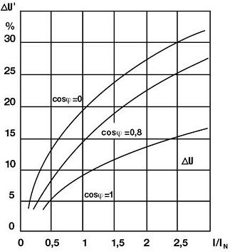 |
Illustration 5
Voltage Dip in Dependence of Starting Current and Power Factor |
Connection of Asynchronous Motors
Special dynamic loads occur when large asynchronous motors with squirrel
cage rotors are connected. Through the compoundising system with higher
current the excitation is also increased so that the connection of
asynchronous motors is only limited by the drive and the switchgear with
the connected loads. Short time current reductions up to 20 % do not
cause any problems under normal circumstances.
If relatively large squirrel cage motors have to be connected directly
then the following circumstances have to be taken into consideration
when the plant is designed and the set is selected:
- Is the
driving machine of the generator capable of producing the increased
generator drive power short time at a certain starting factor of the
asynchronous motor?
- How big can
the voltage collapse become without affecting voltage dependent loads,
switchgear etc. in a detrimental way?
- Will the
torque of the asynchronous motor be sufficient at voltage drops during
the start?
- Guide values
for the connection of Asynchronous motors are as follows:
- Motor
Power/kW approx. 15 % of the Generator Type Power/kVA: ΔU' ca. 20 %
- Motor
Power/kW approx. 30 % of the Generator Type Power/kVA: ΔU' ca. 30 %
- With
star/delta-connection three times the motor powers can be used.
In special drive applications the following start up methods are
recommended:
Frequency Start-up
If the generator is supplying an asynchronous motor that has nearly the
same power then the full speed running can be achieved by connecting the
load when the Diesel set is at a standstill. Subsequently the Diesel
engine is started and gradually run up to its rated speed. With
increasing speed excitation of the generator takes place and it takes
the asynchronous motor along with it up to its rated speed.
Voltage Start-up
The de-excitation of the generator takes place at full speed (see
section 3.15). The asynchronous motors is connected in a voltageless
condition and another excitation of the generator takes place again. The
motor starts up with increasing voltage.
In both cases the pre-requisite is a separate mains for the motor and
start-up without counter-torque or with fan or pump curve and also a
constant auxiliary voltage for the switchgear.
Transformer Connection
Voltage start-up should be selected for transformers with the same power
in order to avoid the inrush / starting current.
3.9. U/f-Regulation
The R10-KF regulator permits a frequency proportional U/f voltage
control below the rated speed.
Below a cutoff frequency the generator voltage sinks. Above this value
the voltage does not depend on frequency.
When a load is connected to a Diesel set then a short collapse of the
generator voltage occurs and the speed of the motor drops. Since the
stabilization period for the voltage is considerably shorter than the
stabilization period for the speed (approx. 1 : 10) the connected
electrical load is practically constant without influencing the voltage
whilst the counter-torque for the motor increases additionally because
of the speed reduction.
Contrary to that the frequency dependent voltage control removes the
load from the motor during the stabilization phase and reduces the
stabilization period. Ill. 6 shows the progression of the voltage,
torque and speed with and without U/f voltage control. When large loads
in proportion to the driving motor power are connected - specifically
with motors with turbo loaders - there is the possibiliy to improve the
load take-over behaviour of the Diesel sets and to increase the
permissible connection power. The R10-KF regulator can be fitted onto
the SE Types subsequently without modifications.
 |
Illustration 6
Voltage, Torque and Speed Behaviour by Switching on without (A) and
with (B) U/f Voltage Control |
3.10. Short Circuit Behavior
The shock short circuit current complies with DIN VDE 60034-1. The
required short circuit protection of the generators is ensured. Please
consult us if you require generator data for the short circuit
calculation. With a three phase terminal short circuit the generator
produces a stable continous (permanent) short circuit current of at
least 3.5 x IN.
The continuous short circuit current has to be switched off after a
maximum of 5 s.
The two phase short circuit current is approx. 1.5 times and the one
phase approximately 2 times of the continuous short circuit current.
The shock short circuit current dies away quickly and transforms into
the continuous short circuit current after approx. 100 - 150 ms. In
order to adhere to the protective measures a continuous short circuit
current of up to 5 x IN may be necessary in special cases. In
these cases please consult us for special agreement.
Short circuit currents are absolute values that refer to the rated
powers; please take into consideration at power deratings!
3.11. Asymmetric Load
It is permissible to supply asymmetric mains as long as the current
does not exceed the rated value in any phase. Here it has to be taken
into consideration that the voltage deviation, voltage form and the
power data no longer reach the rated values. Thus the voltage asymmetry
is approx. ± 5 % with a single phase load with rated current and two
no-load phases or with two phase rated current and one no-load phase. To
ensure optimum operating conditions an as even as possible division of
the currents onto the three phases should always be aimed at.
3.12. Static Inverter Load
Static inverters are non-linar loads the connection of which leads to
a distortion of the voltage curve, which results in increased generator
losses and which possibly impaires the functionality of the other
connected loads. In order to keep the consequences of the static
inverter load as small as possible the generators are designed in a
special way for this. An effective damper winding, 2/3 chording,
particularly small subtransient reactances (xd'') and according to the
type of load also a larger generator type ensure an optimum operation.
Pre-requisite for the sizing is the knowledge of the plant that is being
designed. If possible the following should therefore be stated when
placing the order:
- share /
portion of the static inverter load of the total load
- current
distortion factor
- Inverter
type (3, 6, 12 phase inverter)
- type of the
static inverter load (Drives, communicationequipment,battery loading
etc.)
Permissible voltage distortion factor of the plant Guide values for
the sizing of the generator are as follows:
- Inverter 12
pulse approx. 80 %,
- Inverter 6
pulse approx. 70 %,
- Inverter for
variable speed approx. 50 % of the rated power with standard winding.
3.13. Parallel Operation
All generators have a damper cage and are designed for parallel
operation. Through the fitted statics device the voltage curves in
dependency on load current and power factor receive a slighly falling
characteristic to the power proportional reactive load distribution. The
voltage statics can be set up to a max. of 6 % (refered to cosφ = 0.8).
The prerequisite for a stable parallel operation with power proportional
active load division is that the speed regulator of the driving machines
is designed accordingly.
3.13.1. Synchronisation
The parallel connection of the generators can be performed using the
known synchronisation methods. The voltage, frequency and phase position
have to be brought in line.
Following deviations before the connection are permissible:
- voltage
difference max. 10 % of UN
- frequency
deviation max. 2 % of fN
- error angle
max. 15° referred to 180° between two zero transits of the voltage
float/hover
For hand synchronisation a better frequency alignment is required!
Since mechanical damage can occur on the generator and the set please
ensure that false synchronisations are avoided at all times.
3.13.2. Starting Synchronisation
Certain mains replacement plant must be capable of operation for max.
of 15 s (VDE 01108), i.e. after mains failure the emergency power supply
must take over the complete power output within this period of time. For
plant with several sets this period of time is not sufficient for the
driving machines to reach the full speed, for excitation to take place
and for the subsequent synchronisation to be carried out. This can be
shortened considerably by using start-up synchronisation. With
generators of the SE series the start-up synchronisation for the same
generators is possible. (With different types please consult the
manufacturer.) In this case the generators are connected parallel by
means of an equalization lead prior to the start (s. 3.13.4.), are run
up to speed jointly, during which they pull themselves in a synchronous
phase position at excitation.
3.13.3. Parallel Operation of the identical AEM
Generators
|
Table 6 - Actual Operating Diagram of Gensets |
| |
Effect in
single operation |
Main
effect in parallel operation |
|
Voltage set point of generator rise |
Generator
voltage rise |
Generator
supply more reactive power |
|
Voltage set point of generator drop |
Generator
voltage drop |
Generator
supply less reactive power |
|
Speed set point of drive rise |
Frequency
rise |
Generator
supply more active power |
|
Speed set point of drive drop |
Frequency
drop |
Generator
supply less active power |
Parallel operation of generators of any type is ensured with the aid
of the statics device. The statics of approx. 2 % (referred to the
no-load voltage; at rated current and power factor cosφ = 0.8) that is
set in the factory ensures a correct parallel operation. Thus the
required even distribution of the reactive load onto the individual
generators is achieved. The statics can be set using the relevant
potentiometer on the regulator. No additional measures are required on
the switchgear.
3.13.4. Parallel Operation of the identical AEM
Generators
This is possible without any problems using an equalization lead. For
this the stator windings of the excitation machines have to be joined
after synchronisation. A proportional active load division leads
inevitably to a corresponding reactive load distribution. The voltage
tolerance remains unchanged compared to single operation. The statics
are not necessary.
3.13.5. Parallel Operation with Generators of
other Manufactures
For this the generators must have a damper cage and the excitaiton
device must be suitable for parallel operation. A correct distribution
of the reactive load requires that all generators have a statics device
and practically corresponding falling voltage curves can be set.
If the star points are connected then through differences in the voltage
form it may be necessary to fit a choke in the star point conductor.
3.13.6. Mains Parallel Operation
To ensure a stable parallel operation of a Genset with rigid mains it
is necessary to avoid an overload at changing mains conditions and at
the same time utilise the power to the highest possible extent. As far
as the active load is concerned this is done by means of the speed
regulator or an electronic load distribution. As far as the reactive
load is concerned it can be carried out either by means of the statics
device or by means of a power factor dependent regulator (cosφ
regulator/please take the power limitation according to Table 4 into
consideration! )
Regarding the limitation of the current in the start point conductor see
Section 2.11.
- Mains
Parallel Operation with Statics
In order to prevent reactive power overload of a generator at the
mains the generator voltage must be lowered by the statics device at
increasing reactive load (also see Section 3.13.).
- Mains
Parallel Operation with cosφ Regulator (R10-KC, R9-C Regulator)
At constant operation at mains a special cosφ regulator can be
supplied for reactive current regulation. Apart from the normal
voltage regulation it also allows the regulation of the power factor
cosφ independently on the active load of the Genset and on the changes
of the mains voltage at the infeed point. A cosφ regulator can also be
fitted subsequently without any modifications being required.
3.14. Self Excitation
This occurs through remanence in the magnetic circuit of the
excitation machine. On start up the excitation of the generator to the
rated voltage is carried out through this within approx. 2 - 5 s. In
special cases the build-up can be shortened by e.g. special construction
or when an external voltage is applied short time to the stator winding
of the excitation machine.
3.15. De-excitation
The generator with running engine de-excite if:
- on the SE
types with compoundising device the lead-out terminals (+,-) of the
stator winding of the excitation machines are short circuited;
- on the SH
types with direct regulation the auxiliary winding are switched off on
the terminals in the terminal box.
On the generator terminals there remains only a residual voltage at
the rate of the remanence voltage.
3.16. Overvoltage Protection and Emergency Manual
Operation
- The
compoundisation principle with step down regulation that is used for
the excitation of the SE types has the advantage that in the event of
the regulator failing the excitation current is limited by the choke
and the voltage cannot exceed the 1.1 times rated value. If a spare
regulator is not available then an emergency operation at a voltage
deviation of approx. ±3 % that is not limited in time can be
implemented. To do this a variable resistance (approx. 150 Ω, 2 Amp)
has to be connected in parallel to the stator winding of the
excitation machine after the regulator has been disconnected; this can
be used to set the required voltage. Fur-ther instructions are
contained in the Operating Instructions for the Excitation Device.
- With the
generator types with direct regulation (SH-types) a fuse in the
regulator protects the generators against an excessive voltage
increase in the event of the regulator failing. The generator is
de-energised when the fuse responds. An emergency manual control can
be implemented by connecting a settable external voltage of approx. 50
V DC.
3.17. Behaviour at Underspeed
Underspeed of the driving machine (e.g. warm up running, measurements
on motor) is possible without any time limitations:
- On the SE
types the choke limits the excitation current so that even without U/f
regulation a speed dependent terminal voltage appears. A load
application onto the generator at partial speed is possible with
limitations due to the reduced ventilation.
- With the SH
types with direct regulation the regulator contains a U/f function
that limits the excitation
3.18. Vibrations
In the standard version the Generators comply with vibration grade N
according to DIN ISO 2373. Version in Grades R or S can be agreed. The
permissible vibration load through the drive and the installation site
is as follows:
|
10 Hz |
s ≤ 0,4
mm |
|
10 - 100 Hz |
Veff
≤ 18 mm/s |
|
> 100 Hz |
b ≤ 1,6
g |
Please consult us if higher values occur.
3.19. Vibrations
The limit values according to DIN EN 60034-9 are complied with.
3.20. Interference Suppression
In the standard version the Interference Suppression Grade N
according to DIN VDE 0875 is guaranteed. Interference Suppression Grade
K against enquiry. |
From Wikipedia, the free encyclopedia

Three-phase power transformer which is the sole transfer point
for electricity to a suburban shopping mall in Canada. Note the four
wires used for the 208 V/120Y service: one is for the neutral, and
the other three are for the X, Y, and Z phases.

Three Phase Electric Power Transmission
Three-phase is a common method of
electric power
transmission. It is a type of
polyphase system used to power motors and many other devices.
This article deals with where, how and why "three phase" is used. For
information on the basic
mathematics and principles of three phase see
three-phase. For information on testing three phase equipment (kit)
please see
three-phase testing.
Three phase systems may or may not have a
neutral wire. A neutral wire allows the three phase system to use a
higher voltage while still supporting lower voltage
single phase appliances. In high voltage distribution situations it is
common not to have a neutral wire as the loads can simply be connected
between phases (phase-phase connection).
Three phase has properties that make it very desirable in electric
power systems. Firstly the phase currents tend to cancel one another
(summing to zero in the case of a linear balanced load). This makes it
possible to eliminate the neutral conductor on some lines. Secondly power
transfer into a linear balanced load is constant, which helps to reduce
generator and motor vibrations. Finally, three-phase systems can produce a
magnetic field that rotates in a specified direction, which simplifies the
design of electric motors. Three is the lowest
phase order to exhibit all of these properties.
Most
domestic loads are single phase. Generally three phase power either
does not enter domestic
houses at
all, or where it does, it is split out at the main
distribution board.
The three phases are typically indicated by colors which vary by
country. See the table for more information.
Generation and distribution
Condiitions for connections of two generators
same rotating phases
same frequence
same voltage
phases inside of a defined window at closing

Animation of three-phase power flow
At the
power station, an
electrical generator converts mechanical power into a set of
alternating
electric currents, one from each electromagnetic coil or winding of
the generator. The currents are
sinusoidal functions of time, all at the same
frequency but with different
phases. In a three-phase system the phases are spaced equally, giving
a phase separation of 120°. The frequency is typically 50
Hz in
Europe and 60 Hz in the US and Canada (see
List of countries with mains power plugs, voltages and frequencies).
Generators output at a voltage that ranges from hundreds of volts to
30,000 volts. At the power station,
transformers "step-up" this voltage to one more suitable for
transmission.
After numerous further conversions in the transmission and distribution
network the power is finally transformed to the standard mains voltage
(i.e. the "household" voltage). The power may already have been split into
single phase at this point or it may still be three phase. Where the
stepdown is 3 phase, the output of this transformer is usually star
connected with the standard mains voltage (120
V in North
America and 230 V in Europe) being the phase-neutral voltage. Another
system commonly seen in North America is to have a delta connected
secondary with a centre tap on one of the windings supplying the
ground and neutral. This allows for 240 V three phase as well as three
different single phase voltages (120 V between two of the phases and the
neutral, 208 V between the third phase (known as a wild leg) and neutral
and 240 V between any two phases) to be made available from the same
supply.
Single-phase loads
Single-phase loads may be connected to a three-phase system, either by
connecting across two live conductors (a phase-to-phase connection), or by
connecting between a phase conductor and the system
neutral, which is either connected to the center of the Y (star)
secondary winding of the supply transformer, or is connected to the center
of one winding of a delta transformer (Highleg Delta system). (see
Transformer#Polyphase transformers and
Split phase ) Single-phase loads should be distributed evenly between
the phases of the three-phase system for efficient use of the supply
transformer and supply conductors.
The line-to-line voltage of a three-phase system is √3 times the line
to neutral voltage. Where the line-to-neutral voltage is a standard
utilization voltage, (for example in a 240 V/415 V system) individual
single-phase utility customers or loads may each be connected to a
different phase of the supply. Where the line-to-neutral voltage is not a
common utilization voltage, for example in a 347/600 V system,
single-phase loads must be supplied by individual step-down transformers.
In multiple-unit residential buildings in North America, lighting and
convenience outlets can be connected line-to-neutral to give the 120 V
utilization voltage, and high-power loads such as cooking equipment, space
heating, water heaters, or air conditioning can be connected across two
phases to give 208 V. This practice is common enough that 208 V
single-phase equipment is readily available in North America. Attempts to
use the more common 120/240 V equipment intended for
three-wire single-phase distribution may result in poor performance
since 240 V heating equipment will only produce 75% of its rating when
operated at 208 V.
Where three phase at low voltage is otherwise in use, it may still be
split out into single phase service cables through joints in the supply
network or it may be delivered to a master
distribution board (breaker panel) at the customer's premises.
Connecting an electrical circuit from
one phase to the neutral generally supplies the country's standard
single phase voltage (120 VAC or 230 VAC) to the circuit.
The power transmission grid is organized so that each phase carries the
same magnitude of current out of the major parts of the transmission
system. The currents returning from the customers' premises to the last
supply transformer all share the neutral wire, but the three-phase system
ensures that the sum of the returning currents is approximately zero. The
delta wiring of the primary side of that supply transformer means that no
neutral is needed in the high voltage side of the network.
Connecting phase-to-phase
Connecting between two phases provides √3 or 173% of the single-phase
voltage (208 VAC in US; 400 VAC in Europe) because the out-of-phase
waveforms add to provide a higher peak voltage in the resulting waveform.
Such connection is referred to as a line to line connection and is
usually done with a two-pole circuit breaker. This kind of connection is
typically used for high-power appliances, because it can provide nearly
twice as much power for the same current. This allows more power to be
supplied for a given wire size. This may also allow loads to be served
that would otherwise be so large as to exceed the capability of the
building's wiring. Existing wiring can be reconnected to provide the
higher voltage to the load. In USA, for example, where the single-phase
voltage is 120 V, a 2 kW 208 volt electric
baseboard heater could require use of a phase-phase connection where
only standard wiring exists. (Note that electrical codes typically would
require wire color coding to be readjusted in this case.)
Three-phase loads
The most important class of three-phase load is the
electric motor. A three phase induction motor has a simple design,
inherently high starting torque, and high efficiency. Such motors are
applied in industry for pumps, fans, blowers, compressors, conveyor
drives, and many other kinds of motor-driven equipment. A three-phase
motor will be more compact and less costly than a single-phase motor of
the same voltage class and rating; and single-phase AC motors above 10 HP
(7.5 kW) are uncommon. Three phase motors will also vibrate less and hence
last longer than single phase motor of the same power used under the same
conditions.
Large
air conditioning equipment (for example, most York units above 2.5
tons (8.8 kW) cooling capacity) use three-phase motors for reasons of
efficiency , economy and longevity.
Resistance heating loads such as electric
boilers
or space heating may be connected to three-phase systems. Electric
lighting may also be similarly connected. These types of loads do not
require the revolving magnetic field characteristic of three-phase motors
but take advantage of the higher voltage and power level usually
associated with three-phase distribution.
Large
rectifier systems may have three-phase inputs; the resulting DC
current is easier to filter (smooth) than the output of a single-phase
rectifier. Such rectifiers may be used for battery charging,
electrolysis processes such as aluminum production, or for operation
of DC motors.
An interesting example of a three-phase load is the
electric arc furnace used in steelmaking and in refining of ores.
In much of Europe stoves are designed to allow for a three phase feed.
Usually the individual heating units are connected between phase and
neutral to allow for connection to a single phase supply where this is all
that is available.
Phase converters
Occasionally the advantages of three-phase motors make it worthwhile to
convert single-phase power to three phase. Small customers, such as
residential or farm properties may not have access to a three-phase
supply, or may not want to pay for the extra cost of a three-phase
service, but may still wish to use three-phase equipment. Such converters
may also allow the frequency to be varied allowing speed control. Some
locomotives are moving to multi-phase motors driven by such systems even
though the incoming supply to a locomotive is nearly always either DC or
single phase AC.
Because single-phase power is interrupted at each moment that the
voltage crosses zero but three-phase delivers power continuously, any such
converter must have a way to store energy for the necessary fraction of a
second.
One method for using three-phase equipment on a single-phase supply is
with a
rotary phase converter, essentially a three-phase motor with special
starting arrangements and power factor correction that produces balanced
three-phase power. When properly designed these rotary converters can
allow satisfactory operation of three-phase equipment such as machine
tools on a single phase supply. In such a device, the energy storage is
performed by the mechanical
inertia
(flywheel effect) of the rotating components.
Another method often attempted is with a device referred to as a
static phase converter. This method of running three phase equipment
is commonly attempted with motor loads though it only supplys 2/3 power
and can cause the motor loads to run hot and in some cases overheat. This
method will not work when any circuitry is involved such as cnc devices,
or in induction and rectifier type loads.
Some devices are made which create an imitation three-phase from
three-wire single phase supplies. This is done by creating a third
"subphase" between the two live conductors, resulting in a phase
separation of 180° − 90° = 90°. Many three-phase devices will run on this
configuration, but at lower efficiency.
It can be valuable to look up the various ratings of 3 phase converter
technology with the
US Phase Converter Standards Organization. They regulate the standards
of phase converters manufactured in the US and provide ratings on various
technologies used to convert single phase power to three phase power.
Variable frequency drives (also known as solid-state
inverters)
are used to provide precise speed and torque control of three phase
motors. Some models can be powered by a single phase supply. VFDs work by
converting the supply voltage to DC and converting the DC to a suitable
three phase source for the motor. The drives usually include large
capacitors to smooth out supply variations and zero crossing states.
Small scale applications
While most three-phase motors are very big (>750w), there are small
(<50w) three-phase motors. The most common example is a computer fan. An
inverter circuit inside the fan converts DC to three-phase AC. This is
done to decrease noise (as the torque from a three-phase motor is very
smooth compared to that from a single phase motor or a brushed DC motor)
and increase reliability (as there are no brushes to wear out, unlike a
brushed DC motor).
Alternatives to three-phase
-
Three-wire single-phase distribution is useful when
high voltage three phase is not available, and allows double the
normal utilization voltage to be supplied for high-power loads.
-
Two phase power, like three phase, gives constant power transfer to
a linear load. For loads which connect each phase to neutral, assuming
the load is the same power draw , the two wire system has a neutral
current which is greater than neutral current in a three phase system.
Also motors aren't entirely linear and this means that despite the
theory motors running on three phase tend to run smoother than those on
two phase. The generators at
Niagara Falls installed in 1895 were the largest generators in the
world at the time and were two-phase machines. True two-phase power
distribution is essentially obsolete. Special purpose systems may use a
two-phase system for control. Two-phase power may be obtained from a
three-phase system using an arrangement of
transformers called a Scott T.
- Monocyclic power was a name for an asymmetrical modified
two-phase power system used by
General Electric around 1897 (championed by
Charles Proteus Steinmetz and
Elihu Thomson; this usage was reportedly undertaken to avoid patent
legalities). In this system, a generator was wound with a full-voltage
single phase winding intended for lighting loads, and with a small
(usually 1/4 of the line voltage) winding which produced a voltage in
quadrature with the main windings. The intention was to use this "power
wire" additional winding to provide starting torque for induction
motors, with the main winding providing power for lighting loads. After
the expiration of the Westinghouse patents on symmetrical two-phase and
three-phase power distribution systems, the monocyclic system fell out
of use.
- High phase order systems for power transmission have been built and
tested. Such transmission lines use 6 or 12 phases and design practices
characteristic of extra-high voltage transmission lines. High-phase
order transmission lines may allow transfer of more power through a
given transmission line right-of-way without the expense of a
HVDC
converter at each end of the line.
Color codes
Conductors of a three phase system are usually identified by a color
code, to allow for balanced loading and to assure the correct phase
rotation for
induction motors. Colors used may adhere to old standards or to no
standard at all, and may vary even within a single installation. However,
the current National Electrical Code (2005) does not require any color
identification of conductors other than that of the neutral (white or
white with a color stripe), the ground (green or green with a yellow
stripe), and, in the case of a High Leg Delta system, the High Leg ("shall
be durably and permanently marked by an outer finish that is orange in
color or by other effective means"). (NEC 110.15).
| |
L1 |
L2 |
L3 |
Neutral |
Ground |
| North America |
Black |
Red |
Blue |
White |
Green |
| North America (newer 277/480 installations) |
Brown |
Orange |
Yellow |
White |
Green |
| UK until April 2006 (colours in brackets are Harmonised colours) |
Red (Brown) |
Yellow (prev. white) (Black) |
Blue (Grey) |
Black (Blue) |
Green/yellow striped (green on very old installations, approx.
before 1970) |
| Europe (including UK) from April 2004 |
Brown |
Black |
Grey |
Blue |
Green/yellow striped |
| Previous European (varies by country) |
Brown or black |
Black or brown |
Black or brown |
Blue |
Green/yellow striped |
| Europe, for
busbars |
Yellow |
Green |
Purple |
– |
– |
| Australia |
Red |
White (prev. yellow) |
Blue |
Black |
Green/yellow striped (green on very old installations) |
Note that in the U.S. a green/yellow striped wire typically indicates
an
Isolated ground.
|
 |
 |
 |
 |
 |
 |
 |
THE COLOURS DO NOT
CORRESPOND LEFT AND RIGHT
BLEUE IS OK
RED LEFT
IS
BLACK RIGHT
YELLOW LEFT IS
RED RIGHT |
| DIRECT
PHASES ROTATION |
|
|
|
|
|
| INVERSE PHASES ROTATION |
PARALLELE OPERATION FORBIDDEN |
SYNCHRONISING AND CONNECTION GIVE A SHORT CIRCUIT |
|
|
|
|
Variable setup and basic definitions

One voltage cycle of a three-phase system, labelled 0 to 360° ( 2 π
radians) along the time axis. The plotted line represents the variation of
instantaneous voltage (or current) with respect to time. This cycle will
repeat 50 or 60 times per second, depending on the power system frequency.
The colours of the lines represent the American color code for
three-phase. That is black=VL1 red=VL2 blue=VL3
Let
-

where t is time and
f is frequency.
Using x = ft the waveforms for the
three phases are
-

-

-

where A is the peak voltage and the voltages on L1, L2 and L3 are measured
relative to the
neutral.
Balanced loads
Generally, in electric power systems the loads are distributed as evenly as
practical between the phases. It is usual practice to discuss a balanced system
first and then describe the effects of unbalanced systems as deviations from the
elementary case.
To keep the calculations simple we shall normalise A and R to 1 for the
remainder of these calculations
Star connected systems with neutral
Constant power transfer
An important property of three-phase power is that the power available to a
resistive load,
 ,
is constant at all times.
,
is constant at all times.
Using : R = 1 and
A = 1
-

-

-

-

-

Using
angle subtraction formulae
-

-

-

-

-

Using the
Pythagorean trigonometric identity
-

since we have eliminated x we can see that the total power does not vary with
time. This is essential for keeping large generators and motors running
smoothly.
No neutral current
The neutral current is the sum of the phase currents.
Using : R = 1 and A
= 1
-

-

-

-

-

Using
angle subtraction formulae
-

-
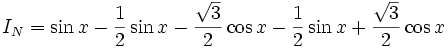
-

Star connected systems without neutral
Since we have shown that the neutral current is zero we can see that removing
the neutral core will have no effect on the circuit, provided the system is
balanced. In reality such connections are generally used only when the load on
the three phases is part of the same piece of equipment (for example a
three-phase motor), as otherwise switching loads and slight imbalances would
cause large voltage fluctuations.
Three-Phase
Three-phase AC is not hard to understand if you use a phasor
diagram
Most alternating-current (AC) generation and transmission, and a good part of
use, take place through three-phase circuits. If you want to understand electric
power, you must know something about three-phase. It is rather simple if you go
at it the right way, though it has a reputation for difficulty.
Phase is a frequently-used term around AC. The word comes from Greek
fasis, "appearance," from fanein,
"to appear." It originally referred to the eternally regular changing appearance
of the moon through each month, and then was applied to the periodic changes of
some quantity, such as the voltage in an AC circuit. Electrical phase is
measured in degrees, with 360° corresponding to a complete cycle. A sinusoidal
voltage is proportional to the cosine or sine of the phase.
Three-phase, abbreviated 3φ, refers to three voltages or currents that
that differ by a third of a cycle, or 120 electrical degrees, from each other.
They go through their maxima in a regular order, called the phase sequence.
The three phases could be supplied over six wires, with two wires reserved for
the exclusive use of each phase. However, they are generally supplied over only
three wires, and the phase or line voltages are the voltages between the three
possible pairs of wires. The phase or line currents are the currents in each
wire. Voltages and currents are usually expressed as rms or effective values, as
in single-phase analysis.
When you connect a load to the three wires, it should be done in such a way
that it does not destroy the symmetry. This means that you need three equal
loads connected across the three pairs of wires. This looks like an equilateral
triangle, or delta, and is called a delta load. Another symmetrical connection
would result if you connected one side of each load together, and then the three
other ends to the three wires. This looks like a Y, and is called a wye load.
These are the only possibilities for a symmetrical load. The center of the Y
connection is, in a way, equidistant from each of the three line voltages, and
will remain at a constant potential. It is called the neutral, and may be
furnished along with the three phase voltages. The benefits of three-phase are
realized best for such a symmetrical connection, which is called balanced.
If the load is not balanced, the problem is a complicated one one whose solution
gives little insight, just numbers. Such problems are best left to computer
circuit analysis. Three-phase systems that are roughly balanced (the practical
case) can be analyzed profitably by a method called symmetrical components.
Here, let us consider only balanced three-phase circuits, which are the most
important anyway.
 The key to understanding three-phase is to understand the phasor diagram for the
voltages or currents. In the diagram at the right, a, b and c represent the
three lines, and o represents the neutral. The red phasors are the line or delta
voltages, the voltages between the wires. The blue phasors are the wye voltages,
the voltages to neutral. They correspond to the two different ways a symmetrical
load can be connected. The vectors can be imagined rotating anticlockwise with
time with angular velocity ω = 2πf, their projections on the horizontal axis
representing the voltages as functions of time. Note how the subscripts on the
V's give the points between which the voltage is measured, and the sign of the
voltage. Vab is the voltage at point a relative to point b, for
example. The same phasor diagram holds for the currents. In this case, the line
currents are the blue vectors, and the red vectors are the currents through a
delta load. The blue and red vectors differ in phase by 30°, and in magnitude by
a factor of √3, as is marked in the diagram.
The key to understanding three-phase is to understand the phasor diagram for the
voltages or currents. In the diagram at the right, a, b and c represent the
three lines, and o represents the neutral. The red phasors are the line or delta
voltages, the voltages between the wires. The blue phasors are the wye voltages,
the voltages to neutral. They correspond to the two different ways a symmetrical
load can be connected. The vectors can be imagined rotating anticlockwise with
time with angular velocity ω = 2πf, their projections on the horizontal axis
representing the voltages as functions of time. Note how the subscripts on the
V's give the points between which the voltage is measured, and the sign of the
voltage. Vab is the voltage at point a relative to point b, for
example. The same phasor diagram holds for the currents. In this case, the line
currents are the blue vectors, and the red vectors are the currents through a
delta load. The blue and red vectors differ in phase by 30°, and in magnitude by
a factor of √3, as is marked in the diagram.
Suppose we want to take two phase wires and neutral to make a three-wire
household service supplying 120 V between each hot wire and ground. The neutral
will become the grounded conductor, the two phases the hot conductors. Then, the
wye voltage is 120, so the delta voltage will be √3 x 120 = 208 V. This is the
three-phase line voltage necessary in this case. Note that the two 120 V sources
are not opposite in phase, and will not give 240 V between them. On the other
hand, suppose we do want a 240 V service. Then this must be the line voltage,
and the voltages to neutral will be 139 V, not 120 V. A 120 V three-phase
service will give only 69 V from line to neutral. Note that √3 appears
everywhere, and that the differences in phase explain the unexpected results.
If the load consists of general impedances Z, the situation is described by
current and voltage phasors connected by V = IZ, both in magnitude and phase.
The diagrams are similar in shape, and rotated by the phase angle between
voltage and current in each impedance. Remember that the line voltages are the
red vectors, while the line currents are the blue vectors. Z relates either the
line voltages and delta currents, or the wye voltages and the line currents,
depending on the connection. Z does not relate the line current and line
voltage, which are different in phase by 30° even for unity power factor (pure
resistance load).
This comes out more clearly when we consider the power P delivered to the
load. For a resistive delta load, P = 3 VlineIdelta = √3 VlineIline,
since Idelta = √3 Iline. For a wye load, P = 3 VwyeIline
= √3 VlineIline. This is, of course, the same expression.
For other than unity power factor, this must be multiplied by cos θ, which is
the angle of Z, not the phase difference between the line voltage and line
current. This means, most emphatically, that our usual rule for finding the
power from phasors does not apply to three-phase!
If you write out the three phase currents as explicit functions of time, Imaxcos
ωt, Imaxcos (ωt - 120°) and Imaxcos (ωt + 120°), square
them, multiply by the resistance R, and add, the result is the constant (3/2)Imax2R
= 3 I2R. The power is applied steadily as in DC circuits, not in
pulses as in single-phase AC circuits. This is a great advantage, giving
three-phase machines 48% greater capacity than identical single-phase machines.
In Germany and Switzerland, where three-phase power was originated and
developed, it is known as Drehstrom, "rotating current" for this property
of constant power. Ordinary AC is called Wechselstrom, or "change
current." Nikola Tesla, the discoverer of polyphase currents and inventor of the
induction motor, employed two-phase current, where the phase difference is 90°.
This also can be used to create a rotating magnetic field, and is more efficient
than single-phase, but is not quite as advantageous as three-phase. Two-phase
power was once rather common in the United States, where Tesla was important in
the introduction of AC, but has now gone completely out of use.
Two-phase can be supplied over three wires, but there is no true neutral,
since the phases are not symmetrical. However, it is always easy to double the
number of phases in a transformer secondary by making two secondary windings and
connecting them in opposing phases. Four-phase does have a neutral, like
three-phase, but requires four wires. In fact, three-phase is more economical
than any other number of phases. For applications like rectifiers and
synchronous converters where DC is produced, it is most efficient to use
six-phase AC input, which is easily produced from three-phase in a transformer.
If you are transmitting a certain amount of power single-phase, adding one
more conductor operated at the same line voltage and current and using
three-phase will increase the power transmitted by 72% with only a 50% increase
in the amount of copper and losses. The advantage is obvious. Under certain
conditions, transmitting a certain amount of power by three-phase only requires
75% of the copper of single-phase transmission. This is not the major advantage
of three-phase, but it does play a factor.
Three wires are usually seen in high-voltage transmission lines, whether on
towers or poles, with pin or suspension insulators. Some high-voltage lines are
now DC, since solid state devices make it easier to convert to and from AC. The
DC lines are free of the problems created by phase, as well as eliminating the
skin effect that reduces the effective area of the conductors. It is not nearly
as easy to manage long-distance electrical transmission as might be thought.
Unbalanced systems
Practical systems rarely have perfectly balanced loads, currents, voltages or
impedances in all three phases. The analysis of unbalanced cases is greatly
simplified by the use of the techniques of
symmetrical components. An unbalanced system is analyzed as the
superposition of three balanced systems, each with the positive, negative or
zero sequence of balanced voltages.
Revolving magnetic field
Any polyphase system, by virtue of the time displacement of the currents in
the phases, makes it possible to easily generate a magnetic field that revolves
at the line frequency. Such a revolving magnetic field makes polyphase
induction motors possible. Indeed, where induction motors must run on
single-phase power (such as is usually distributed in homes), the motor must
contain some measure to produce a revolving field, otherwise the motor cannot
generate any stand-still
torque and will
not start. The field produced by a single-phase winding can provide energy to a
motor already rotating, but without auxiliary functions the motor will not
accelerate from a stop when energized.
Conversion to other phase systems
Provided two voltage waveforms have at least some relative displacement on
the time axis, other than a multiple of a half-cycle, any other
polyphase set of voltages can be obtained by an array of passive
transformers. Such arrays will evenly balance the polyphase load between the
phases of the source system. For example, balanced two-phase power can be
obtained from a three-phase network by using two specially constructed
transformers, with taps at 50% and 86.6% of the primary voltage. This
Scott T connection produces a true two-phase system with 90° time
difference between the phases. Another example is the generation of
higher-phase-order systems for large
rectifier
systems, to produce a smoother
DC
output and to reduce the
harmonic
currents in the supply.
When three-phase is needed but only single-phase is readily available from
the utility company a phase converter can be used to generate three-phase power
from the single phase supply. The
US Phase Converter Standards Organization conducts independent three phase
tests on the various phase converter technologies and publishes the results.
If the frequency (HZ) of the three-phase power supplied does not match the
frequency needed to run the machines or equipment a
Frequency converter can be used
|
|
|
The power of alternating current (AC) fluctuates. For domestic use for
e.g. light bulbs this is not a major problem, since the wire in the
light bulb will stay warm for the brief interval while the power drops.
Neon lights (and your computer screen) will blink, in fact, but faster
than the human eye is able to perceive. For the operation of motors etc.
it is useful, however, to have a current with constant power.
Voltage Variation for Three Phase Alternating Current

It is indeed possible to obtain constant power from an AC system by
having three separate power lines with alternating current which run in
parallel, and where the current phase is shifted one third of the cycle,
i.e. the red curve above is running one third of a cycle behind the blue
curve, and the yellow curve is running two thirds of a cycle behind the
blue curve.
As we learned on the previous page, a full cycle lasts 20 milliseconds
(ms) in a 50 Hz grid. Each of the three phases then lag behind the
previous one by 20/3 = 6 2/3 ms.
Wherever you look along the horizontal axis in the graph above, you will
find that the sum of the three voltages is always zero, and that the
difference in voltage between any two phases fluctuates as an
alternating current.
On the next page
you will see how we connect a generator to a three phase grid.
|
| |
© Copyright 1997-2003 Danish Wind Industry Association
Updated 12 May 2003
http://www.windpower.org/en/stat/unitsac3.htm
|

| |
Synchronous Generators
3-Phase Generator (or Motor) Principles
 All
3-phase generators (or motors) use a rotating magnetic field.
In the picture to the left we have installed three electromagnets
around a circle. Each of the three magnets is connected to its own
phase in the
three phase electrical grid.
As you can see, each of the three
electromagnets alternate between producing a South pole and a
North pole towards the centre. The letters are shown in black when the
magnetism is strong, and in light grey when the magnetism is weak. The
fluctuation in magnetism corresponds exactly to the fluctuation in
voltage of each phase. When one phase is at its peak, the other two
have the current running in the opposite direction, at half the
voltage. Since the timing of current in the three magnets is one third
of a cycle apart, the magnetic field will make one complete revolution
per cycle.
Synchronous Motor Operation
The compass needle (with the North pole painted red) will follow the
magnetic field exactly, and make one revolution per cycle. With a 50
Hz grid, the needle will make 50 revolutions per second, i.e. 50 times
60 = 3000 rpm (revolutions per minute).
In the picture above, we have in fact managed to build what is called
a 2-pole permanent magnet synchronous motor. The reason why it is
called a synchronous motor, is that the magnet in the centre will
rotate at a constant speed which is synchronous with (running exactly
like the cycle in) the rotation of the magnetic field.
The reason why it is called a 2-pole motor is that it has one North
and one South pole. It may look like three poles to you, but in fact
the compass needle feels the pull from the sum of the magnetic fields
around its own magnetic field. So, if the magnet at the top is a
strong South pole, the two magnets at the bottom will add up to a
strong North pole.
The reason why it is called a permanent magnet motor is that the
compass needle in the centre is a permanent magnet, not an
electromagnet. (You could make a real motor by replacing the compass
needle by a powerful permanent magnet, or an electromagnet which
maintains its magnetism through a coil (wound around an iron core)
which is fed with direct current).
The setup with the three electromagnets is called the stator in the
motor, because this part of the motor remains static (in the same
place). The compass needle in the centre is called the rotor,
obviously because it rotates.
Synchronous Generator Operation
If you start forcing the magnet around (instead of letting the current
from the grid move it), you will discover that it works like a
generator, sending alternating current back into the grid. (You should
have a more powerful magnet to produce much electricity). The more
force (torque) you apply, the more electricity you generate, but the
generator will still run at the same speed dictated by the frequency
of the electrical grid.
You may disconnect the generator completely from the grid, and start
your own private 3-phase electricity grid, hooking your lamps up to
the three coils around the electromagnets. (Remember the principle of
magnetic /
electrical induction from the reference manual section of this web
site). If you disconnect the generator from the main grid, however,
you will have to crank it at a constant rotational speed in order to
produce alternating current with a constant frequency. Consequently,
with this type of generator you will normally want to use an
indirect
grid connection of the generator.
In practice, permanent magnet synchronous generators are not used very
much. There are several reasons for this. One reason is that permanent
magnets tend to become demagnetised by working in the powerful
magnetic fields inside a generator. Another reason is that powerful
magnets (made of rare earth metals, e.g. Neodynium) are quite
expensive, even if prices have dropped lately.
Wind Turbines With Synchronous Generators
Wind turbines which use synchronous generators normally use
electromagnets in the rotor which are fed by direct current from the
electrical grid. Since the grid supplies alternating current, they
first have to convert alternating current to direct current before
sending it into the coil windings around the electromagnets in the
rotor.
The rotor electromagnets are connected to the current by using brushes
and slip rings on the axle (shaft) of the generator.
|
| |
© Copyright 1997-2003 Danish Wind Industry Association
Updated 19 September 2003
http://www.windpower.org/en/tour/wtrb/syncgen.htm
|
Three-phase Y and Δ configurations
Three-phase Y and Δ configurations
Initially we explored the idea of three-phase power systems by connecting
three voltage sources together in what is commonly known as the "Y" (or "star")
configuration. This configuration of voltage sources is characterized by a
common connection point joining one side of each source:
If we draw a circuit showing each voltage source to be a coil of wire
(alternator or transformer winding) and do some slight rearranging, the "Y"
configuration becomes more obvious:
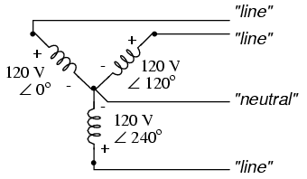
The three conductors leading away from the voltage sources (windings) toward
a load are typically called lines, while the windings themselves are
typically called phases. In a Y-connected system, there may or may not be
a neutral wire attached at the junction point in the middle, although it
certainly helps alleviate potential problems should one element of a three-phase
load fail open, as discussed earlier:

When we measure voltage and current in three-phase systems, we need to be
specific as to where we're measuring. Line voltage refers to the
amount of voltage measured between any two line conductors in a balanced
three-phase system. With the above circuit, the line voltage is roughly 208
volts. Phase voltage refers to the voltage measured across any one
component (source winding or load impedance) in a balanced three-phase source or
load. For the circuit shown above, the phase voltage is 120 volts. The terms
line current and phase current follow the same logic: the former
referring to current through any one line conductor, and the latter to current
through any one component.
Y-connected sources and loads always have line voltages greater than phase
voltages, and line currents equal to phase currents. If the Y-connected source
or load is balanced, the line voltage will be equal to the phase voltage times
the square root of 3:

However, the "Y" configuration is not the only valid one for connecting
three-phase voltage source or load elements together. Another configuration is
known as the "Delta," for its geometric resemblance to the Greek letter of the
same name (Δ). Take close notice of the polarity for each winding in the drawing
below:

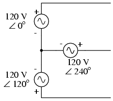
At first glance it seems as though three voltage sources like this would
create a short-circuit, electrons flowing around the triangle with nothing but
the internal impedance of the windings to hold them back. Due to the phase
angles of these three voltage sources, however, this is not the case.
One quick check of this is to use Kirchhoff's Voltage Law to see if the three
voltages around the loop add up to zero. If they do, then there will be no
voltage available to push current around and around that loop, and consequently
there will be no circulating current. Starting with the top winding and
progressing counter-clockwise, our KVL expression looks something like this:

Indeed, if we add these three vector quantities together, they do add up to
zero. Another way to verify the fact that these three voltage sources can be
connected together in a loop without resulting in circulating currents is to
open up the loop at one junction point and calculate voltage across the break:

Starting with the right winding (120 V ∠ 120o) and progressing
counter-clockwise, our KVL equation looks like this:

Sure enough, there will be zero voltage across the break, telling us that no
current will circulate within the triangular loop of windings when that
connection is made complete.
Having established that a Δ-connected three-phase voltage source will not
burn itself to a crisp due to circulating currents, we turn to its practical use
as a source of power in three-phase circuits. Because each pair of line
conductors is connected directly across a single winding in a Δ circuit, the
line voltage will be equal to the phase voltage. Conversely, because each line
conductor attaches at a node between two windings, the line current will be the
vector sum of the two joining phase currents. Not surprisingly, the resulting
equations for a Δ configuration are as follows:

Let's see how this works in an example circuit:

With each load resistance receiving 120 volts from its respective phase
winding at the source, the current in each phase of this circuit will be 83.33
amps:

So, the each line current in this three-phase power system is equal to 144.34
amps, substantially more than the line currents in the Y-connected system we
looked at earlier. One might wonder if we've lost all the advantages of
three-phase power here, given the fact that we have such greater conductor
currents, necessitating thicker, more costly wire. The answer is no. Although
this circuit would require three number 1 gage copper conductors (at 1000 feet
of distance between source and load this equates to a little over 750 pounds of
copper for the whole system), it is still less than the 1000+ pounds of copper
required for a single-phase system delivering the same power (30 kW) at the same
voltage (120 volts conductor-to-conductor).
One distinct advantage of a Δ-connected system is its lack of a neutral wire.
With a Y-connected system, a neutral wire was needed in case one of the phase
loads were to fail open (or be turned off), in order to keep the phase voltages
at the load from changing. This is not necessary (or even possible!) in a
Δ-connected circuit. With each load phase element directly connected across a
respective source phase winding, the phase voltage will be constant regardless
of open failures in the load elements.
Perhaps the greatest advantage of the Δ-connected source is its fault
tolerance. It is possible for one of the windings in a Δ-connected three-phase
source to fail open without affecting load voltage or current!

The only consequence of a source winding failing open for a Δ-connected
source is increased phase current in the remaining windings. Compare this fault
tolerance with a Y-connected system suffering an open source winding:

With a Δ-connected load, two of the resistances suffer reduced voltage while
one remains at the original line voltage, 208. A Y-connected load suffers an
even worse fate with the same winding failure in a Y-connected source:

In this case, two load resistances suffer reduced voltage while the third
loses supply voltage completely! For this reason, Δ-connected sources are
preferred for reliability. However, if dual voltages are needed (e.g. 120/208)
or preferred for lower line currents, Y-connected systems are the configuration
of choice.
- REVIEW:
- The conductors connected to the three points of a three-phase source or
load are called lines.
- The three components comprising a three-phase source or load are called
phases.
- Line voltage is the voltage measured between any two lines in a
three-phase circuit.
- Phase voltage is the voltage measured across a single component in
a three-phase source or load.
- Line current is the current through any one line between a
three-phase source and load.
- Phase current is the current through any one component comprising a
three-phase source or load.
- In balanced "Y" circuits, line voltage is equal to phase voltage times the
square root of 3, while line current is equal to phase current.
-
- In balanced Δ circuits, line voltage is equal to phase voltage, while line
current is equal to phase current times the square root of 3.
-
- Δ-connected three-phase voltage sources give greater reliability in the
event of winding failure than Y-connected sources. However, Y-connected
sources can deliver the same amount of power with less line current than
Δ-connected sources.
Three-phase power systems
Three-phase power systems
Split-phase power systems achieve their high conductor efficiency and
low safety risk by splitting up the total voltage into lesser parts and powering
multiple loads at those lesser voltages, while drawing currents at levels
typical of a full-voltage system. This technique, by the way, works just as well
for DC power systems as it does for single-phase AC systems. Such systems are
usually referred to as three-wire systems rather than split-phase
because "phase" is a concept restricted to AC.
But we know from our experience with vectors and complex numbers that AC
voltages don't always add up as we think they would if they are out of phase
with each other. This principle, applied to power systems, can be put to use to
make power systems with even greater conductor efficiencies and lower shock
hazard than with split-phase.
Suppose that we had two sources of AC voltage connected in series just like
the split-phase system we saw before, except that each voltage source was 120o
out of phase with the other:

Since each voltage source is 120 volts, and each load resistor is connected
directly in parallel with its respective source, the voltage across each load
must be 120 volts as well. Given load currents of 83.33 amps, each load must
still be dissipating 10 kilowatts of power. However, voltage between the two
"hot" wires is not 240 volts (120 ∠ 0o - 120 ∠ 180o)
because the phase difference between the two sources is not 180o.
Instead, the voltage is:
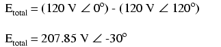
Nominally, we say that the voltage between "hot" conductors is 208 volts
(rounding up), and thus the power system voltage is designated as 120/208.
If we calculate the current through the "neutral" conductor, we find that it
is not zero, even with balanced load resistances. Kirchhoff's Current Law
tells us that the currents entering and exiting the node between the two loads
must be zero:


So, we find that the "neutral" wire is carrying a full 83.33 amps, just like
each "hot" wire.
Note that we are still conveying 20 kW of total power to the two loads, with
each load's "hot" wire carrying 83.33 amps as before. With the same amount of
current through each "hot" wire, we must use the same gage copper conductors, so
we haven't reduced system cost over the split-phase 120/240 system. However, we
have realized a gain in safety, because the overall voltage between the two
"hot" conductors is 32 volts lower than it was in the split-phase system (208
volts instead of 240 volts).
The fact that the neutral wire is carrying 83.33 amps of current raises an
interesting possibility: since it's carrying current anyway, why not use that
third wire as another "hot" conductor, powering another load resistor with a
third 120 volt source having a phase angle of 240o? That way, we
could transmit more power (another 10 kW) without having to add any more
conductors. Let's see how this might look:

A full mathematical analysis of all the voltages and currents in this circuit
would necessitate the use of a network theorem, the easiest being the
Superposition Theorem. I'll spare you the long, drawn-out calculations because
you should be able to intuitively understand that the three voltage sources at
three different phase angles will deliver 120 volts each to a balanced triad of
load resistors. For proof of this, we can use SPICE to do the math for us:

120/208 polyphase power system
v1 1 0 ac 120 0 sin
v2 2 0 ac 120 120 sin
v3 3 0 ac 120 240 sin
r1 1 4 1.44
r2 2 4 1.44
r3 3 4 1.44
.ac lin 1 60 60
.print ac v(1,4) v(2,4) v(3,4)
.print ac v(1,2) v(2,3) v(3,1)
.print ac i(v1) i(v2) i(v3)
.end
VOLTAGE ACROSS EACH LOAD
freq        v(1,4)      v(2,4)      v(3,4)
6.000E+01   1.200E+02   1.200E+02   1.200E+02
VOLTAGE BETWEEN "HOT" CONDUCTORS
freq        v(1,2)      v(2,3)      v(3,1)
6.000E+01   2.078E+02   2.078E+02   2.078E+02
CURRENT THROUGH EACH VOLTAGE SOURCE
freq        i(v1)       i(v2)       i(v3)
6.000E+01   8.333E+01   8.333E+01   8.333E+01
Sure enough, we get 120 volts across each load resistor, with (approximately)
208 volts between any two "hot" conductors and conductor currents equal to 83.33
amps. At that current and voltage, each load will be dissipating 10 kW of power.
Notice that this circuit has no "neutral" conductor to ensure stable voltage to
all loads if one should open. What we have here is a situation similar to our
split-phase power circuit with no "neutral" conductor: if one load should happen
to fail open, the voltage drops across the remaining load(s) will change. To
ensure load voltage stability in the even of another load opening, we need a
neutral wire to connect the source node and load node together:

So long as the loads remain balanced (equal resistance, equal currents), the
neutral wire will not have to carry any current at all. It is there just in case
one or more load resistors should fail open (or be shut off through a
disconnecting switch).
This circuit we've been analyzing with three voltage sources is called a
polyphase circuit. The prefix "poly" simply means "more than one," as in "polytheism"
(belief in more than one deity), polygon" (a geometrical shape made of
multiple line segments: for example, pentagon and hexagon), and "polyatomic"
(a substance composed of multiple types of atoms). Since the voltage sources are
all at different phase angles (in this case, three different phase angles), this
is a "polyphase" circuit. More specifically, it is a three-phase
circuit, the kind used predominantly in large power distribution systems.
Let's survey the advantages of a three-phase power system over a single-phase
system of equivalent load voltage and power capacity. A single-phase system with
three loads connected directly in parallel would have a very high total current
(83.33 times 3, or 250 amps:

This would necessitate 3/0 gage copper wire (very large!), at about
510 pounds per thousand feet, and with a considerable price tag attached. If the
distance from source to load was 1000 feet, we would need over a half-ton of
copper wire to do the job. On the other hand, we could build a split-phase
system with two 15 kW, 120 volt loads:
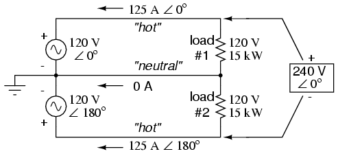
Our current is half of what it was with the simple parallel circuit, which is
a great improvement. We could get away with using number 2 gage copper wire at a
total mass of about 600 pounds, figuring about 200 pounds per thousand feet with
three runs of 1000 feet each between source and loads. However, we also have to
consider the increased safety hazard of having 240 volts present in the system,
even though each load only receives 120 volts. Overall, there is greater
potential for dangerous electric shock to occur.
When we contrast these two examples against our three-phase system, the
advantages are quite clear. First, the conductor currents are quite a bit less
(83.33 amps versus 125 or 250 amps), permitting the use of much thinner and
lighter wire. We can use number 4 gage wire at about 125 pounds per thousand
feet, which will total 500 pounds (four runs of 1000 feet each) for our example
circuit. This represents a significant cost savings over the split-phase system,
with the additional benefit that the maximum voltage in the system is lower (208
versus 240).
One question remains to be answered: how in the world do we get three AC
voltage sources whose phase angles are exactly 120o apart? Obviously
we can't center-tap a transformer or alternator winding like we did in the
split-phase system, since that can only give us voltage waveforms that are
either in phase or 180o out of phase. Perhaps we could figure out
some way to use capacitors and inductors to create phase shifts of 120o,
but then those phase shifts would depend on the phase angles of our load
impedances as well (substituting a capacitive or inductive load for a resistive
load would change everything!).
The best way to get the phase shifts we're looking for is to generate it at
the source: construct the AC generator (alternator) providing the power in such
a way that the rotating magnetic field passes by three sets of wire windings,
each set spaced 120o apart around the circumference of the machine:
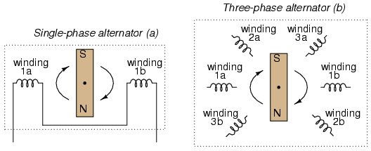
Together, the six "pole" windings of a three-phase alternator are connected
to comprise three winding pairs, each pair producing AC voltage with a phase
angle 120o shifted from either of the other two winding pairs. The
interconnections between pairs of windings (as shown for the single-phase
alternator: the jumper wire between windings 1a and 1b) have been omitted from
the three-phase alternator drawing for simplicity.
In our example circuit, we showed the three voltage sources connected
together in a "Y" configuration (sometimes called the "star" configuration),
with one lead of each source tied to a common point (the node where we attached
the "neutral" conductor). The common way to depict this connection scheme is to
draw the windings in the shape of a "Y" like this:

The "Y" configuration is not the only option open to us, but it is probably
the easiest to understand at first. More to come on this subject later in the
chapter.
- REVIEW:
- A single-phase power system is one where there is only one AC
voltage source (one source voltage waveform).
- A split-phase power system is one where there are two voltage
sources, 180o phase-shifted from each other, powering a two
series-connected loads. The advantage of this is the ability to have lower
conductor currents while maintaining low load voltages for safety reasons.
- A polyphase power system uses multiple voltage sources at different
phase angles from each other (many "phases" of voltage waveforms at work). A
polyphase power system can deliver more power at less voltage with
smaller-gage conductors than single- or split-phase systems.
- The phase-shifted voltage sources necessary for a polyphase power system
are created in alternators with multiple sets of wire windings. These winding
sets are spaced around the circumference of the rotor's rotation at the
desired angle(s).
Technische Stromarten: Gleichstrom, Wechselstrom und Drehstrom
Technische Stromarten:
Gleichstrom
Im einfachsten Fall fließt ein zeitlich konstanter Strom. Einen solchen Strom
nennt man
Gleichstrom (engl. direct current).

techn. und phys. Stromrichtung
Zu beachten ist die Technische Stromrichtung: Vereinbarungsgemäß wird
eine Stromrichtung von Plus nach Minus angenommen. Diese Stromrichtung geht auch
in alle physikalischen Gleichungen ein, die den Strom als solchen betreffen.
Eine elektrische Spannungsdifferenz ist jedoch immer von Plus nach Minus
positiv. Daher ist die technische Stromrichtung sinnvoll und wird üblicherweise
verwendet, damit die Richtung von Strom und Spannung identisch ist. Die
technische Stromrichtung ist nicht zu verwechseln mit der Flussrichtung der
Elektronen (negative Ladungträger), die entgegen der technischen Stromrichtung
fließen. Siehe auch
Technische und physikalische Stromrichtung.
Physikalische Stromrichtung: Um den Mechanismus des Stromflusses zu
verstehen und bestimmte elektrische Eigenschaften von Materialien herzuleiten,
betrachtet man die wirkliche Bewegung der Ladungsträger. In
Metallen
bewegen sich in der Regel
Elektronen,
also negative Ladungsträger, die vom Minus-Pol zum Plus-Pol fließen, denn am
Minus-Pol herrscht ein Überschuss an Elektronen, und/oder am Plus-Pol ein
Mangel, der durch den elektrischen Strom ausgeglichen wird, sobald der
Stromkreis geschlossen wird.
In elektrisch leitfähigen
Flüssigkeiten sind gegebenenfalls positive und negative Ladungsträger oder
reduzierbare und
oxidierbare
Stoffe vorhanden, die sich zu den jeweiligen
Polen hinbewegen. An den Polen werden sie reduziert bzw. oxidiert, nehmen
also an einem Pol Elektronen auf und geben Elektronen an dem anderen Pol ab und
überbrücken dadurch die Übertragung von Elektronen im Stromkreis.
In einem Experiment mit einer wässrigen Lösung zur Feststellung der
Stromrichtung wurde die physikalisch falsche, technische Stromrichtung
ermittelt, da nur die positiven Ladungsträger sichtbar waren, die sich
allerdings auf den Minus-Pol zubewegen.
Ein anderer Fall tritt bei
p-dotierten
Halbleitern
auf: Hier verhalten sich fehlende Elektronen (so genannte Löcher oder
Defektelektronen) wie positive Ladungsträger mit Masse. Da in der
Löcherleitung die Elektronen die Löcher füllen wandern tatsächlich die
Elektronen und hinterlassen an ihrem vorherigen Ort ein Loch. Daher wandern die
Löcher in die entgegengesetzte Richtung der Elektronen.
Als Gleichspannungsquelle kommen
galvanische Zellen (Batterien), entsprechende
Dynamos (zum
Teil mit nachgeschalteter Gleichrichtung),
photovoltaische Zellen (Solaranlagen) oder
Schaltnetzteile in Frage. In der Technik häufig anzutreffen ist auch eine
Kombination von
Transformator und Gleichrichter.
Fällt bei gleich bleibender Stromrichtung die Spannung (und damit, sofern ein
Verbraucher angeschlossen ist, die Stromstärke) periodisch stark ab, so spricht
man von einer pulsierenden Gleichspannung.
Gleichrichter liefern beim Umwandeln von Wechselspannung in Gleichspannung
meist pulsierende Gleichspannung, sofern die Spannung nicht durch
Kondensatoren oder andere Maßnahmen geglättet wird.
Wechselstrom
Drehstrom - die wundersame Dreieinigkeit von drei verketteten Wechselströmen
Neben der Möglichkeit des Ferntransports von elektrischer Energie bietet
Wechselstrom noch weitere Vorteile, wenn er als "Drehstrom" angewendet wird.
Schon bei der ersten Fernübertragung elektrischer Energie, die 1891 anläßlich
der Frankfurter Elektrizitätsausstellung stattfand, wurde davon Gebrauch
gemacht. Auf der Drehstromtechnik basiert heute die gesamte Stromwirtschaft.
Bei Drehstrom handelt es sich um drei Wechselströme, die im selben Generator
erzeugt werden. Die "Phasen" dieser Wechselströme - also das Auf und Ab der
Sinuskurve bei jeder Drehung der Generatorachse um 360 Winkelgrade - sind um
jeweils 120 Winkelgrade gegeneinander versetzt. So entsteht ein dreiphasiger
Wechselstrom, dessen Sinuskurven sich gleichmäßig überlagern. Betrachtet man die
miteinander verketteten Phasen des Drehstroms auf dem Diagramm rechts, wird man
feststellen, daß sich die Ausschläge der Sinuskurven in den positiven oder
negativen Bereich in jedem Augenblick zur Gesamtsumme null ergänzen.
Drehfeld für robuste Motoren
Der Drehstrom verdankt seinen Namen der Anwendung für den Betrieb von
Elektromotoren. Er erzeugt nämlich in den Ständerwicklungen dieser Motoren ein
magnetisches Drehfeld, das den Rotor mitnimmt und so die Drehbewegung des Motors
erzeugt. Dadurch entfällt der verschleißträchtige Stromwender, der beim
Gleichstrommotor auf mechanische Weise für die Stromversorgung und Umpolung des
Magnetfeldes im Rotor sorgen muß. Drehstrommotoren brauchen nicht einmal Bürsten
und Schleifringe. Ihre Rotoren können sich völlig kontaktfrei drehen, wenn sie
den Strom für den Aufbau des Rotorfelds auf induktivem Wege aus dem Magnetfeld
des Ständers beziehen ("Käfigläufer"). Deshalb sind Drehstrommotoren äußerst
robust und leistungsfähig. Dasselbe gilt für Drehstromgeneratoren.
Stern-und Dreieck-Schaltung
Drehstrom benötigt insgesamt drei Leitungen. Das mag auf den ersten Blick
überraschen, da schon für einphasigen Wechselstrom zwei Leitungen erforderlich
sind. Demnach bräuchte man für drei Phasen eigentlich sechs Leitungen. Die
Rückleitungen können jedoch bei Drehstrom entfallen, da sich die drei Phasen in
jedem Augenblick zu null ergänzen. Voraussetzung ist, daß der elektrische
Verbraucher an alle drei Phasen angeschlossen wird und diese gleichmäßig
belastet. Jedes Drehstrom-Gerät setzt sich deshalb aus drei gleichgearteten
elektrischen Teil-Verbrauchern zusammen. Für den Anschluß dieser
Teil-Verbraucher an die drei Phasen gibt es zwei Möglichkeiten:
Stern-Schaltung: Man legt jede Eingangsklemme der drei
Teil-Verbraucher an eine der Phasen und verbindet die Ausgangsklemmen
untereinander.
Dreieck-Schaltung: Die drei Teil-Verbraucher werden jeweils so
zwischen zwei Phasen gelegt, daß jede Ausgangsklemme mit einer Eingangsklemme
verbunden ist.
 |
Bei Stern-Schaltung werden die Eingänge der drei Teilverbraucher des
Drehstromgeräts (rot) mit den Leitern R, S, T und die Ausgänge sternförmig
miteinander verbunden. Im Niederspannungsnetz erhält dadurch jeder der drei
Teilverbraucher die "Strangspannung" von 230 Volt, die zwischen jedem der
drei Leiter und dem gemeinsamen Sternpunkt besteht.
|
 |
Bei Dreieck-Schaltung werden die Ein- und Ausgänge der drei
Teilverbraucher in Form eines Dreiecks miteinander verbunden. Zugleich wird
jede "Spitze" des Dreiecks an eine der drei Phasen gelegt. Im
Niederspannungsnetz erhält so jeder der Teilverbraucher die "Leiterspannung"
von 400 Volt, die jeweils zwischen zwei der drei Phasen-Leiter besteht.
|
Je nach Art der Schaltung verketten sich die Stromstärken der drei Phasen
oder deren Spannungen. So läßt sich zum Beispiel aus demselben Drehstrom durch
Sternpunkt-Schaltung eine Spannung von 230 Volt oder durch Dreieck-Schaltung
eine Spannung von 400 Volt gewinnen.
Die Transformatoren, die der Strom auf seinem Weg vom Kraftwerk zur Steckdose
passieren muß, sind entweder im Stern oder Dreieck geschaltet. Zum Beispiel
verwendet man beim Übergang von der Mittel- auf die Niederspannung üblicherweise
die Dreiecksschaltung für die Oberspannungs-Seite des Transformators (30 kV oder
10 kV) und die Sternschaltung für die Niederspannungs-Seite (400/230 Volt).

Wenn elektrische Geräte im Stern oder im Dreieck an die drei
Drehstrom-Leiter R, S und T angeschlossen werden, ist eine Rückleitung nicht
erforderlich, da R, S und T gleichmäßig (symmetrisch) belastet werden.
Voraussetzung ist natürlich, daß die drei Teilverbraucher des
Drehstromgeräts exakt dieselben Leistungswerte haben.
|

Einphasige Wechselstromgeräte können auf diese Weise an die drei
Drehstrom-Leiter angeschlossen werden. Allerdings werden dadurch R, S und T
ungleichmäßig belastet. Damit die Unsymmetrien keine störenden Auswirkungen
haben, ist der "Neutralleiter" N als Rückleiter erforderlich. Er ist mit der
Stromquelle (Generator oder Transformator) in deren Sternpunkt verbunden und
wurde deshalb früher auch als "Mittelpunktleiter" bezeichnet. Je nach
Belastung der drei Drehstrom-Leiter fließt im Neutralleiter ein
Ausgleichsstrom.
|
Der Endverbraucher kann seine elektrischen Geräte wahlweise in Sternschaltung
(mit 230 Volt) oder in Dreiecksschaltung (mit 400 Volt) betreiben. Die dafür
erforderlichen Steckdosen erkennt man an den drei Kontakten für die drei
Phasen-Leiter (außerdem verfügen sie über den üblichen Schutzkontakt). Eine
besondere Führungs-"Nase" gewährleistet, daß die Phasen beim Einstöpseln des
Steckers übereinstimmen. Beim Vertauschen der Phasen laufen Drehstrommotoren
nämlich rückwärts, was unliebsame Folgen haben kann.
Drehstrom-Steckdosen und drehstromtaugliche Geräte findet man aber
normalerweise nur in Gewerbe- und Industriebetrieben. In Haushalten sind sie auf
Ausnahmefälle beschränkt, etwa auf einen besonderen "Kraft"-Anschluß für
Waschmaschinen oder leistungsstarke Heizgeräte.
Das Prinzip der Drehstrom-Übertragung ist seit über hundert Jahren
unverändert

Diese Abbildung zeigt das Prinzip der Drehstromübertragung, wie es F.
A. Haselwander 1888 in seiner Patentanmeldung skizziert hat: Links der
Generator, rechts der Motor; dazwischen die beiden Trafos, die den Strom für
den Transport über die Fernleitungen (Strichel-Linien in der Mitte) erst
hoch- und dann wieder heruntertransformieren. Dieses Prinzip ist bis heute
unverändert gültig.
Übrigens hatte Haselwander mit seiner Patentanmeldung nicht viel Glück:
Zunächst verschlampte sein Anwalt die Anmeldung, dann wurde sie wegen
angeblicher Unklarheiten in der Beschreibung beanstandet und schließlich aus
formalen Gründen zurückgewiesen. Als es ihm später doch noch gelang, seine
Erfindung schützen zu lassen, wurde das Patent auf die Klage eines
Elektrounternehmens hin für ungültig erklärt.
|
 |

Tony Locker |
|
|
Director,
Business Development
I-Gard
(888) 737-4787
Email |
 |
Tony Locker received a BSEE from Rose-Hulman
Institute of Technology and a MSEE from Georgia Institute of Technology.
He is presently Director, Business Development with I-Gard, Cincinnati,
Ohio, where he is responsible for providing technical seminars and
application assistance on resistance grounding and ground fault
protection in the USA. Prior to joining I-Gard in 2005, he was Vice
President – Engineering with Post Glover Resistors. Previously, he was
Director of Engineering at Power Engineering Technology. His background
includes leading design teams and managing installations of numerous
multi-million dollar control and power systems for data centers,
industrial plants, cogeneration facilities, and utilities. Before Power
Engineering Technology, he was a R&D engineer for Square D Company.
Mr. Locker is active in the Industry Applications and Power Engineering
Societies of IEEE, where he serves on several Subcommittees and Working
Groups, as well as NSPE. He is a registered Professional Engineer in
Ohio and has two patents.
|
|
|
| Q. |
|
When a current of 100A is passing through
the phase, what will be the status of neutral and ground, will the
same current will be passing even from them,,,,,
|
|
|
| A. |
|
I am assuming that you are referring to a
single-phase circuit (because ideally no current would be flowing in a
three-phase circuit a solidly grounded system. In a single-phase
circuit, the “flowing” current must flow to the load via the phase
conductor and return via the neutral conductor. So, the current flow
must return via the neutral conductor (in your case, 100A). The ground
conductor should not have any current. In fact, this is how a GFCI
works on a single-phase circuit. Generally speaking, both the phase
and neutral conductors are fed thru a window CT. The current (from the
source) in the phase conductor (100A) produces a flux in the CT in one
direction, and the current in the neutral (traveling the other way
back to the source) produces a flux in the CT in the other direction.
The net result … 0 flux IF the currents are the same. If the currents
are not, the flux will not be the same and a voltage will be generated
by the CT, which can be detected by a relay. The most common way for a
difference in current is current returning back to source via ground
conductor. So, if the phase conductor is 100A and the neutral is 95A,
5A must be traveling back to source via ground conductor. (This will
be detected by the CT and relay.) Zero-sequence CT’s will the same
way, except all three phase conductors are fed thru one window CT,
which measures the net flux. If the current traveling down one
conductor returns thru the other two, then the net flux is 0. If some
current returns thru ground conductor, then the net flux is NOT 0 and
a ground fault relay will alarm.
|
|
|
| Q. |
|
Dear Sir,
In over network Main Circuit breaker Tripped due to one small Circuit
Photo Cell Short Circuit occurred. In this circuit having 05 NOS
Circuit Breakers having different rating like 20Amps, 50Amps,
100Amps,350Amps,1600Amps and 2000Amps. So, Main 2000Amps tripped on
Ground Tripped set 1200Amps set as @ 0.4 and time 0.1 sec, We can
change/increase this setting? On safe side. Our Natural & Ground is
same. Not Repeat this trip or no?
|
|
|
| A. |
|
Unfortunately this is a common problem with
solidly grounded systems. Per the National Electric Code 230-95,
Ground Fault Protection is required for solidly grounded systems <600V
and >1000A. The maximum setting is 1200A and 1sec. If I understand
your question, you have a 1200A GFI set at 0.4, or 480A at 0.1sec.
With this setting, you are hoping that a downstream circuit breaker
(CB) clears the fault before the main circuit breaker (MCB) does.
Since I do not know the manufacturer and type of CB’s, I am going to
use IEC 60898-1 to check coordination. The instantaneous trip at
0.1sec can range from 5 to 20 times rated current. So, let’s look at
each downstream CB that you mentioned: 20A * 5 = 100A 20A * 20 = 400A
(20A CB will trip prior to MCB) 50A * 5 = 250A 50A * 20 = 1000A (50A
CB may or may not trip prior to MCB) 100A * 5 = 500A 100A * 20 = 2000A
(100A CB will not trip prior to MCB) 350A * 5 = 1750A 350A * 20 =
7000A (350A CB will not trip prior to MCB) As you can see, your system
does not appear to be coordinated i.e. a 100A CB will not clear a low
level ground fault before the MCB. What causes a low level ground
fault? An arcing fault is resistive in nature, so an arcing ground
fault is ~35% of a bolted fault. Often times, the fault current will
not be high enough to for the CB to react quickly to trip. The result
is a low magnitude fault current that lasts until the MCB clears as
shown above ONLY IF you are lucky. If not, the fault escalates into a
severe arc flash / blast incident. It is estimated that 85-95% of all
electrical faults are ground faults, which typically start out as an
arcing fault. There are several ways to solve your problem. 1) You
could increase your current setting and/or time. Even though this may
help with coordination, your system has become less safe. Your
exposure to Arc Flash / Blast will significantly increase. The base
equation below shows that an increase in time is directly proportional
to an increase in energy and an increase in current is proportional by
the square. Energy = Current * Current * Resistance * time 2) A better
solution is to install Zone-Selective Interlocking Protection (see our
Application Guide on MGFR relays http://www.i-gard.com/appguides.htm).
This will prevent the MCB from unwanted tripping on a ground fault
downstream AND significantly reduces your exposure to Arc Flash /
Blasts.
|
|


